













TIG welding: choosing the current, equipment and settings
TIG welding (GTAW) is an arc process that uses a non-consumable tungsten electrode and protective gas. The input material, when needed, is introduced separately, allowing the heat of the arc and the added metal to be controlled independently.
The quality of a TIG bond begins before the arc is lit: by identifying the material, preparing the joint and selecting appropriate protection.
This guide links these decisions to the controls of the equipment and to the problems that may appear during the welding. The aim is to understand what to modify, why and what to check after.
For steel and stainless is usually used TIG DC with negative electrode (DCEN). For aluminium, the usual option in manual TIG is AC. Titanium is normally welded into DCEN and requires special attention to the cleaning and protection of hot areas.
1. What the TIG does and when it should be used
This separation allows independent control of the arc heat and the amount of metal added. It is useful in thin sheet, pipe roots, stainless components and works where precision and finishing matter.
It's interesting when...
You need to control the bathroom, access small joints or limit finishing work. It allows welding with input or, when the union and procedure allow, without it.
Another option should be considered when...
The priority is to deposit large quantities of metal quickly. In some manufactures TIG is used for root and another process for filling.
The process does not generate castor scum. However, A good-looking cord does not by itself prove that the bond is correct: There may be a lack of fusion, inclusions or other discontinuities that require additional controls.
The thickness, by itself, also does not decide whether TIG is profitable. They influence part geometry, access, production volume, automation and quality requirements.
2. Start with the material: AC, DC and polarity
| Material | Usual selection | What Needs Attention |
|---|---|---|
| Carbon steel and low alloy steel | DCEN: negative electrode | Degree of steel, preparation and preheating or treatment requirements where applicable. |
| Stainless steel | DCEN | Degree, cleaning, contribution and root protection according to application. |
| Aluminium and its alloys | AC, as usual option in manual TIG | Prior rust cleaning, AC balance and tungsten compatibility with the source. |
| Titanium and its alloys | DCEN | Root protection and additional protection of hot areas when required by the procedure. |
| Magnesium and its alloys | Usually AC | Identification of alloy and specific preparation, input and welding procedure. |
General process selections, not manufacturing recipes. The final choice depends on the material, the union and the applicable procedure.
What DCEN Means
In DCEN, tungsten works connected to the negative pole and the return connection of the piece to the positive. The manufacturer's scheme must always be checked. The Weld Return Connection does not replace the equipment’s protective earth connection.
What does the AC do?
In AC, the negative electrode (EN) and positive (EP) phases are alternated. The AC balance sheet modifies the proportion of time of these phases and allows adjusting the compromise between rust cleaning and tungsten thermal behavior. It does not replace the cleaning of the piece.
Before copying a percentage, check if the team expresses the balance as % EN, % EP or cleaning: the same number can represent different settings. The AC output frequency is another control and should not be confused with the high arc ignition frequency.
AC does not imply continuous HF. In certain modern inverter, the high frequency is used to initiate the arc and electronics then maintains its stability. The concrete solution depends on the equipment.
3. Choose the team for the real job
A continuous current delivery machine does not necessarily offer all the functions of a dedicated TIG equipment. Check the supported process, boot method and compatible accessories before connecting a torch.
| What to check | Why it Matters |
|---|---|
| DC or AC/DC output | It must correspond to the material and procedure envisaged. |
| Low intensity stability | It imports in thin sheet and at the beginning and end of the cord. |
| Intensity and cycle of work | The maximum number of amperes does not indicate how long that current can be maintained. Compare values declared under equivalent conditions. |
| HF, Lift TIG or other supported boot | The arc ignition procedure influences the ease of initiation and the risk of contamination. |
| Gas control and sequence | Pregás, posgas and ramps allow to manage start and finish. |
| Torch and cooling | The declared capacity of the torch for current, gas, cycle of work and type of cooling must be respected. |
| Pedal, remote control and 2T/4T modes | They must be compatible with the equipment. The exact functioning of each sequence is consulted in your manual. |
Two Solter teams to relate theory to their controls
The choice between DC and AC/DC can be understood by two examples from the Solter range: ICONTIG DC PRO to work continuously and AEROTIG AC/DC Wi of 200 A when you also need alternate. The current documentation of the latter uses the name AeroTIG PRO 200 AC/DC TFT.
| Reference model | Application in this guide | Controls that help understand the process |
|---|---|---|
| ICONTIG DC PRO TIG DC · 10–220 A | Preparation and control of a steel or stainless bond in DCEN. | Home HF or by contact, 2T/4T modes, pregas, posgas, ramps and pulsed current. |
| AEROTIG AC/DC Wi · 200 A · 1Ph TIG AC/DC · 10–200 A | Comparison of one DC application with one aluminium application in AC. | In addition to the TIG sequence, AC frequency adjustment, balance and tungsten diameter selection. |
Sources: official fact sheets and manuals [1] [2]. The current intervals describe the equipment; they are not recommended values for a particular union.
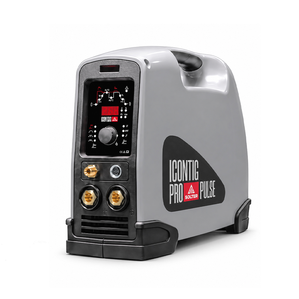
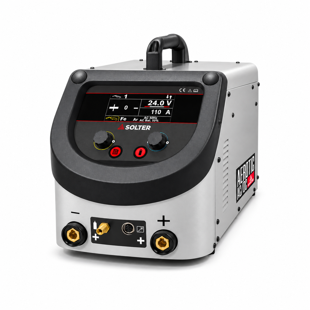
In the ICONTIG, unit indicators allow to distinguish whether the control modifies amperes, time or percentage. In the AEROTIG, the manual defines the AC balance as a percentage of positive cycle time: should not be interpreted as % EN. This detail matters when comparing settings between computers.
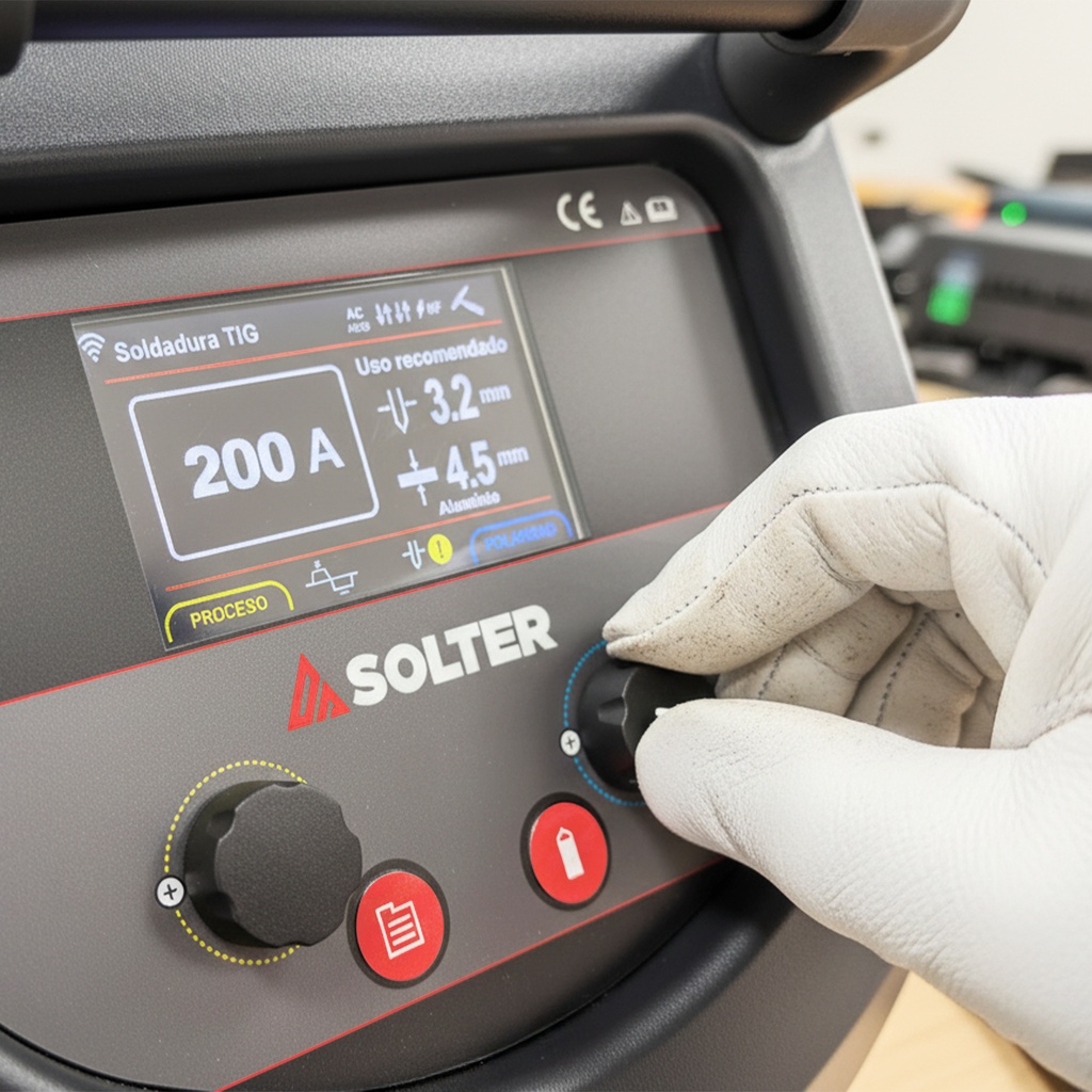
Choose the torch also for access, ergonomics and effective arc time. There is no single ampere threshold requiring liquid cooling in all torches.
4. Tungsten and contribution: two different elections
Select tungsten with your datasheet
Tungsten keeps the arc: is not the input material. Its type, diameter and geometry must correspond to the current, equipment and intensity interval.
Electrodes with lanthanum or cerium are common alternatives for many AC and DC applications, within the conditions of their manufacturer. Those containing thorium present radiological risks and are not presented here as a general starting option.
It identifies the electrode by its designation and composition, in addition to the colour. Avoid moving incomplete tables or mixing manufacturers' codes without verifying their equivalence.
Prepare the tip for the source used
The sharpening is done longitudinally with a medium intended for tungsten and dust control. A tip prepared according to application is common in DC; a truncated tip can also be recommended in AC inverter. It should not be taken for granted that every electrode for AC needs a ball..
If the tip touches the bath or rod and becomes contaminated, stop the welding and recover it according to the preparation procedure. Continuing can compromise arc stability and bonding.
The rod is chosen by the union to be achieved
The selection of the input depends on the base material, the properties required and the service of the part. It is not enough to choose a rod of similar appearance or to always demand a composition identical to that of the base metal.
Keeps the consumable identification, keeps the rods clean and protected and prevents their hot end from coming out of the gas cover during the contribution.
Can you weld without rods? Yes, if the material, the adjustment of the joint and the procedure allow for an autogenic binding. A small thickness, by itself, does not guarantee that the supply can be dispensed with.
5. Gas protection is part of the result
Argon is a regular choice in TIG. There are also helium and mixtures for specific applications. Mixtures with additions such as hydrogen or nitrogen require compatibility with material and procedure; they are not universal alternatives to argon.
Flow, coverage and turbulence
The flow rate is usually expressed in litres per minute and must be checked with the gas circulating. Pressure indicating a gearbox does not equal the flow to the torch.
The choice depends on gas, nozzle, diffuser, tungsten output, gasket and environment. An insufficient flow rate can leave areas unprotected; an excessive flow can lead to turbulence and air inflow.
A gas or gas diffuser Lens can help distribute the flow, but does not compensate for leaks, a damaged nozzle or an incorrect choice of flow.
Protects the root as well when necessary
The back face can rust even if the front of the cord seems right. In stainless and sensitive materials, it defines whether backup gas is needed, how the purge is performed, and what acceptance criteria are applied. Titanium may also require hot-zone drag protection.
Installation security. Protective gases can displace oxygen and create dangerous atmospheres, especially in enclosures and cavities. Purging and work in confined spaces require specific prevention measures.
6. Prepare, test and adjust with an order
Before arcing, prepares eye and body protection, adequate ventilation or extraction, fire control and electrical and gas installation. TIG can generate pollutants, including ozone: little visible fume does not mean lack of exposure.
- Identify the part and the requirement.Record material and degree, thickness, type of joint, position and acceptance criteria. If manufacturing so requires, part of the specification of the welding procedure (WPS).
- Get ready and clean.Eliminates contamination, coatings and cutting debris with the appropriate method. It controls separation, heel and accessibility. Prevent cross-contamination between materials.
- Check equipment and consumables.Confirms process, polarity, return, torch, cooling, tungsten, rod and gas. Check connections and leaks without intervening in the energized interior of the equipment.
- Defines an initial sequence.Adjust current, gas control and ramps according to manual and procedure. Start with a simple configuration before adding functions whose effect you haven't checked.
- Test on a representative test piece.It reproduces material, thickness, bonding and position. Observe bath formation and control, border fusion, root, protection and termination.
- Change a variable and record the effect.A test serves to guide adjustments; final acceptance may require additional inspection and testing.
During the welding, look for a controlled arc, access to the edges and a contribution that does not touch the electrode. The torch and rod orientation should be adapted to the joint and maintain the gaseous cover.
When finished, use the expected current reduction sequence and Keep the torch in position during the posgas. Pulling it away abruptly eliminates protection when tungsten and cord are still hot.
There is no universal amperage per millimeter. A useful table should indicate, at a minimum, alloy, seal, thickness, position, current and polarity, gas, tungsten, input and test conditions. Copying only the amperage eliminates much of the necessary information.
7. TIG pulsed: understands each control
The TIG pulsed alternates between a peak current and a background current. It is used to modulate the bow and the behaviour of the bathroom. Its effect depends on the set of settings and how the cord is made.
| Ctrl | What it describes |
|---|---|
| Peak current | High pulse level. |
| Background current | The low level, which can be shown in amperes or as a percentage of the peak. |
| Pulse rate | How many cycles are produced per second. |
| Peak time or pulse duty | What proportion of the cycle remains at the high level. It's not the heat cycle of the machine. |
For two ideal levels, the average current is calculated by weighting the time of each:
In the example, D = 0,25: 100 × 0,25 + 40 × 0,75 = 55 A. This calculation does not amount to the thermal input of the bond: voltage, speed, waveform and process performance are also involved.
How it applies to the ICONTIG DC PRO. Its manual distinguishes the pulse with A1/T1 and A2/T2 times from the high frequency pulse, adjustable between 10 and 500 Hz. In this second mode, the time is divided to 50 % between both levels; each duration is not modified separately. The example above 25 % explains the overall calculation and does not represent that mode of ICONTIG. [1]
Activating the pulse alone does not guarantee less deformation, greater penetration or more productivity. Results must be compared with defined test conditions.
8. Diagnoses the symptom before changing parameters
The same symptom can have several causes. Start by identifying what has changed and first check preparation, connections, protection and consumables.
| Symptom | What to review first | Moving Forward |
|---|---|---|
| Porosity | Dirt, humidity, leaks, wind, flow rate and gas distribution. | Correct the cause and repeat the test. Increasing undiagnosed gas can make protection worse. |
| Oxidated or deteriorated tungsten | Postgas, coverage, permissible intensity, electrode type and preparation. | Check the supply and recover or replace the electrode before continuing. |
| Erratic arc or difficult start | Return, connections, contaminated tip, process adjustment and start. | Check the manual and electrode conditions. Avoid compensating only with more intensity. |
| Lack of fusion or penetration | Preparation, access, cleaning, current, speed and direction of the arc. | Check the set and check the root and edges with the inspection method required. |
| Bite | Current/speed ratio, orientation and input. | Adjust in a controlled manner and check the profile and acceptance criteria. |
| Tungsten inclusions | Contact with bathroom or rod, overload and tip geometry. | It recovers the electrode and evaluates the binding; improving the tip does not eliminate the inclusion already formed. |
| Oxidized root | Need for backup, purge, leaks and continuity of protection. | It corrects the system and evaluates the degree of oxidation according to material and service. |
| Cracks or final crater | Material and input, joint restrictions, contamination and termination. | Do not apply a universal recipe: the metallurgical cause and the repair procedure should be evaluated. |
If there is overheating of the torch, loss of coolant or damage to cables and hoses, stop the work and check the equipment according to your instructions. Internal interventions are provided by qualified staff.
9. When to move to an advanced solution
Orbital TIG: mechanizes the displacement around the joint, especially in pipe. To achieve repeatability, it requires adequate preparation, alignment, protection and programming; automation does not eliminate the need to verify the result.
TIG with hot wire: electrically preheats the input to increase deposition capacity in appropriate applications. It requires a prepared system and coordination between input and welding parameters.
Consumable inserts: may be part of a defined root preparation. Its geometry and assembly must belong to the union design and procedure, not improvise during work.
10. Frequently asked questions about TIG welding
Is a TIG DC equipment good for aluminium?
In conventional manual TIG, the usual choice for aluminium is an AC/DC team working in AC. There are special procedures in DC, but they do not make any DC machine an equivalent solution for that work.
Titanium needs alternating current?
Not as a general rule. It's usually sold out in DCEN. Cleaning and protecting hot areas are especially important.
Is it better to always use more gas flow?
No. Stable coverage must be achieved with the flow rate appropriate to the configuration. Excess can cause turbulence and drag air.
HF and pulsed TIG mean the same thing?
No. HF refers to the high frequency system used in prime or stabilization, depending on the equipment. The pulse modulates the welding current. The output frequency AC is a different third magnitude.
Are all tungstens prepared the same?
No. The preparation depends on the type of electrode, source and application. Consult the manufacturer's recommendations; the spherical tip is not a universal requirement of the TIG AC.
How do I know what intensity to use?
Part of the applicable manual or procedure and a representative evidence of the union. Material, gasket, position, and speed make a thick figure insufficient to define the process.
Can I check the quality just by looking at the cord?
Visual inspection provides information, but does not detect all discontinuities. The control plan may require root inspection, testing or non-destructive methods.
Define your application before choosing your computer
Material and alloy, thickness range, type of bonding, power supply and working time are a good basis for comparing TIG solutions.
Solter technical documentation
Check the data sheet and the equipment manual for your controls, connections and conditions of use.
- Solter · ICONTIG DC PRO. Product sheet and manual ICONTIG MI-03013-06, 07/2026. Technical data and controls: 3, 8–13 printed pages (PDF pages 4, 9–14).
- Solter · AEROTIG AC/DC Wi 200 A. Product sheet and Manual Aerotig PRO MI03289-03 Spanish, 09/2026. Technical data and AC configuration: 5 and 24 printed pages (PDF pages 6 and 25).
Documentation consulted on the 19 of November of 2026. For each application the equipment manual and the applicable welding procedure must be respected.